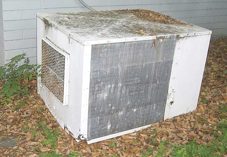
The corner and lower front show how the cabinet has rusted over the years.
The concrete blocks are 4" x 16". This might help in determining the size of the disconnect.
The new unit was installed, but the photos have not yet been posted.
| The following photo represent the original air conditioning system that was installed when the house was built in the mid 50's. The system worked until 2004. Because it had developed a refrigerant leak that would $1,200 just for refrigerant (R-12) and it's age, it was decided to replace the system. |
|
| Condenser. 1 squirrel cage blower. 2 three phase compressors. Compressors were started when the refrigerant pressure dropped because a solenoid valve was opened near the evaporator. There was no low voltage control wiring between the condenser and the thermostat. The corner and lower front show how the cabinet has rusted over the years. |
|
|
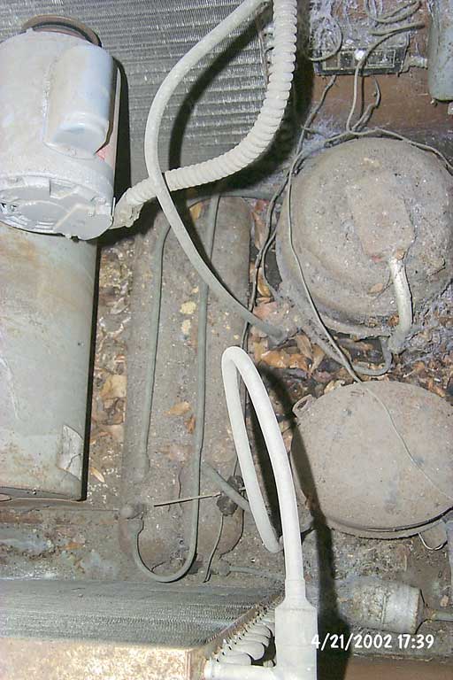
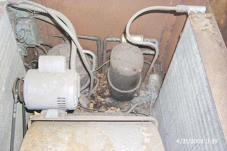
| 1/3 hp blower motor. 2 receivers for refrigerant. One per refrigeration circuit. Top compressor, original. Lower was installed prior to 1977. The newer compressor is the primary. The older would run when the primary could not keep up with the load. Near the top right, one of the two pressure switches and part of the relay that started the compressor. The fan was wired to the primary compressor. |
|
| Every spring, the belt is checked and tightened as necessary. The rear panel is removed and the leaves and any animal nests removed. The typical run cycle was for the unit to come on late April or early May and run until Mid September, 24 hours a day. It did not cycle on or off because the older compressor did not function and it never caught up. The good news, it kept the humidity about 36%. |
|
|
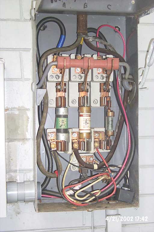
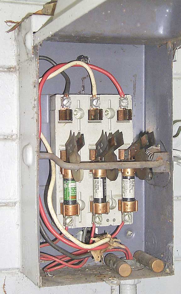
| The main disconnect for the house. Several years ago, a tree fell on the drop between the house and pole taking down the line. The meter box is on the left and plastic conduit was used to connect the two. The box on the bottom is going to the AC condenser. The "A" and "C" fuses are probably the original installed in the 50's. "B" was installed in '77 or '78. "A" & "B" are 150 Amp fuses. "C" 60 Amp. The little black box in the corner is a lightning arrestor The concrete blocks are 4" x 16". This might help in determining the size of the disconnect. |
|
|
| Disconnect for compressors. |
|
|
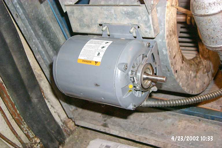
| Blower motor for the air handler. The blower had been making some noise because of the retaining bracket rubbing against the pillow bearing. |
|
|
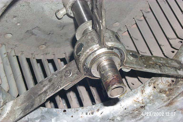
| Flat washers can be seen against the outside of the pillow bearing. Part of the retaining clip can be seen on the inside. You might notice the bolt holding the pillow bearing support in place on the right. The bearing was replaced a few years earlier. |
|
|
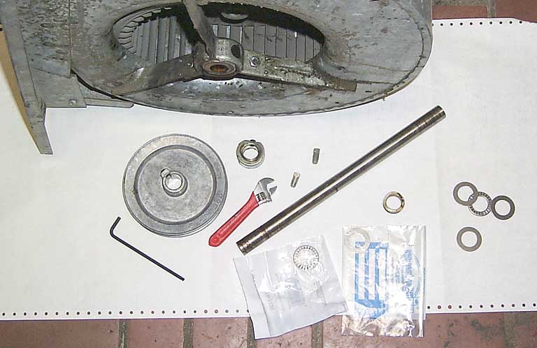
| To keep the blower axle from sliding side to side along its axis, a thrust bearing was placed on each side of the pillow bearing between two washers that came in the package. This stopped the occasional squeak when the blower would slightly shift. The inside retaining clip can be seen above the wrench. |
|
The new unit was installed, but the photos have not yet been posted.
|